A 13 Step Guide to Troubleshooting Hydraulic Systems
Hydraulic systems are complex beasts. They move heavy loads, respond to precise control signals, and endure harsh environments. When something slips like flow drop, heat spikes, sluggish motion, or unusual noise, it’s more than annoying. It’s expensive. The trick is to start where problems usually hide, ask the right questions, and use the most effective tools. Supreme Integrated Technology knows this well. In the spirit of that approach, let’s walk through a detailed guide to diagnosing hydraulic system performance drops: what to check first, how to measure, and how to fix root causes without guesswork.
Why Performance Drops Happen More Often Than You Think
Everything in a hydraulic system, such as fluid, pump, valves, actuators, filters, piping is interconnected. A minor issue in one place often shows up elsewhere. For example:
- Fluid that’s slightly contaminated wears components, which may cause leakage, loss of pressure, or overheating.
- A filter that’s becoming blocked increases temperature and reduces flow, damaging seals or pumps.
- A small internal leak or air entrapment causes spongy or inconsistent motion before any part visibly fails.
Because multiple failure modes can produce similar symptoms, a systematic troubleshooting strategy is essential.
Step 1: Document What You See, Hear, Smell, and Feel
Before grabbing tools or replacing anything, get a clear picture:
- What symptom(s) are showing? Slow actuator, drift, jerky motion, heat, noise?
- When do these symptoms occur (on startup, under load, after warm-up, continuously)?
- What recent work or changes have been done? Fluid change, filter replacement, component swapping.
- What are the environment and operating conditions? Ambient temp, load cycles, shaft speeds, flow rates, pressure levels.
These observations guide what checks to do first. They help distinguish fluid issues from hardware or control issues.
Step 2: Basic Visual and Operational Checks
Start simple. These often catch obvious issues before more expensive diagnostics:
- Check fluid level. Low fluids often cause cavitation, air ingestion, noise, and loss of flow.
- Inspect hoses, lines, and connectors for external leaks. Tighten fittings, inspect seals.
- Look at fluid condition, check for color and clarity. Dark, milky, or cloudy fluid often signals contamination (particles, water, or oxidation).
- Check temperature of fluid and components. Overheating often hints at failing coolers, excessive pressure drops, or heavy-duty cycles.
- Listen for unusual noise: whining, rattling, chatter, cavitation or aeration. Location matters (the pump inlet, return lines, or at valves).
Step 3: Fluid Analysis Comes Early
Fluid is literally “life blood” for hydraulics. Problems in fluid often manifest in many downstream issues. Key tests:
- Viscosity at operating temperature. If fluid is too thin, leakage rises, efficiency drops; if too thick, flow gets restricted and heat builds.
- Water content (ppm or via saturation). Even small amounts of water can reduce lubrication, load capacity, and lead to corrosion.
- Particle contamination count using ISO cleanliness code (ISO 4406 / ISO 11171). Measure particles greater than 4, 6, 14 microns.
- Acid number/oxidation and additive depletion. Dark discoloration, high acid numbers indicate fluid ageing, oxidation.
If fluid fails tests, replacing or reconditioning fluid may be necessary. But always find cause of contamination / degradation, not just its symptoms.
Step 4: Understand ISO Cleanliness Code and Set Targets
If particle contamination is bad, you need to measure it and have clean-oil goals. The ISO 4406 standard gives codes that express contamination levels for >4 µm, >6 µm, >14 µm particles.
Why this matters:
- High particle counts accelerate wear and damage sensitive components (like servo valves, tight tolerance pistons).
- Particle counts double (or more) with each increase in ISO code, meaning even small code jumps represent much more contaminant.
- New oil often isn’t clean enough; drums, bulk oils frequently exceed target ISO codes. Pre-filtration before filling reservoirs is essential.
Setting a cleanliness target depends on system sensitivity. For heavy duty systems, perhaps ISO 19/17/14 is acceptable; for precision valves or high pressures, you need tighter codes like 16/14/11 or better.
Step 5: Pressure, Flow, and Temperature Measurements
After fluid and basics, measure fundamental performance metrics. These tell you where energy (pressure, flow) is being lost.
- Measure system pressure (both at the pump outlet and downstream). Low pressure may indicate pump wear, leaks, relief valve misadjustment.
- Check flow rates. Compare actual flow under different loads to design specs. Restricted flow from clogged filters, lines, or valves will show up.
- Monitor pressure drops across key components: filters, valves, actuators. High drops often signal clogging or restriction.
- Measure temperature at various points: reservoir, pump, fluid return lines. If fluid heats too much, viscosity drops, causing other issues (leakage, wear).
If temperature is high, trace its cause: overloaded system, inefficient cooler, wrong fluid type, high friction or inefficient flow paths.
Step 6: Air Entrainment and Cavitation
Small bubbles can wreak havoc. They cause erratic actuator motion, loss of precision, noise, and damage from cavitation.
- Check if the pump inlet is under vacuum; suction side restrictions, air leaks, loose connections may draw in air.
- Inspect return line positions; ensure return lines are submerged below fluid level. Avoid returning fluid under air.
- Breathers should be proper and clean. If reservoir breathers allow moisture or air, problems follow.
- Cavitation: look for foaming, vapor bubbles, sudden noise under load or transient conditions. This is often caused by low fluid level, improper viscosity, or restricted inlet.
Step 7: Internal and External Leakage
Leaks drain performance silently:
- External leakage: hoses, seals, fittings. Visible, often repairable without dismantling major components.
- Internal leakage: within pumps, across valves, through worn or damaged seals. Symptoms include slower motion, drift, reduced force, drop in pressure under load, but okay at idle.
You can test internal leaks by isolating components, running bypass tests, or measuring drop-off under no load vs loaded conditions.
Step 8: Pump, Valve, and Actuator Health
After confirming fluid, pressure, flow, heat, and leaks, you look at components.
- Pump inspection: For wear in the pump, degraded components manifest in reduced flow, more noise, more heat. Sometimes pumps can be rebuilt. Check inlet conditions; starvation or cavitation lead to damage.
- Valves: Spool valves, relief valves, directional valves. Dirt, sticking, spool misalignment, poor control signals degrade performance. Valve chatter, slow switching, drift.
- Actuators (cylinders, motors): Worn seals cause bypass, leakage, slower response. Inspect for binding, misalignment, air in actuator chambers.
Electrical or control systems may also play a role if valves are electro-hydraulic or electro-proportional. Signal delays, inaccurate sensors or partial failures can mimic hydraulic component faults.
Step 9: Coolers, Heat Exchangers, and Thermal Management
Temperature is a recurring theme. Too hot, and many things go wrong. Consider:
- Are coolers clean and unobstructed? Dirt, debris, or scale on cooler surfaces reduce heat transfer.
- Is flow through cooler sufficient? Check bypass valves, flow paths, and possible blocked lines.
- Are ambient conditions extreme? Hot ambient temperature demands extra cooling capacity or auxiliary cooling.
- Wrong fluid type or viscosity: using oil whose viscosity is high at operating temperature may make it hard for fluid to circulate through cooler or heat exchanger.
Consistent excessive heat accelerates fluid breakdown and seal aging.
Step 10: Filtration Strategy and Reservoir Practices
Even with good filters, poor reservoir and filter practices undermine cleanliness and performance.
- Ensure filters are properly sized (both micron rating and flow capacity), rated for β ratio (efficiency) and absolute vs nominal rating. Oversized filters or poor efficiency can allow for contamination.
- Use side-stream / offline filtration (“kidney-loop”) to continuously polish fluid for particles and remove water when system is running. These systems can dramatically reduce ISO cleanliness codes.
- Clean filling procedures: prefilter added oil, clean caps and filler ports. Use dedicated hoses and containers.
- Reservoir design: minimize turbulence, avoid air entrainment, ensure breathers are clean and rated. Baffle plates help reduce splashing and aeration.
Step 11: Use the Right Tools for Detection
To find less obvious issues, use diagnostic tools that go beyond simple visual checks.
- Particle counters for real-time or periodic monitoring of fluid cleanliness.
- Water measurement tools (Karl Fischer titration method, moisture sensors) to detect free or emulsified water.
- Thermography or IR temperature guns to find hot spots.
- Ultrasonic detection to find internal leaks, cavitation sites or air ingress.
- Pressure and flow sensors at key points to detect drop across filters, valves, or lines.
Step 12: Prioritize Based on Risk, Cost, and Downtime
When everything seems potentially suspect, you must decide what to fix first.
- What failing component would cause the biggest downtime or damage?
- What repairs are easy, cheap, or safe to do now vs costly later?
- What risks exist if you delay? For example, fluid degradation might cause seal failure, which can cause safety hazards.
Often, starting with fluid condition and cleanliness yields the greatest return per effort. Then move to filtration, cooling, and finally component replacements.
Step 13: Lean Toward Preventive & Predictive Maintenance
Once you solve the immediate issue, prevent recurrence by building systems:
- Set up regular fluid sampling and oil analysis programs with proper test frequency based on usage.
- Track ISO cleanliness trends over time. If codes drift upward, you can act before performance drops.
- Train operators to spot early warning signs (temperature, noise, vibration).
- Maintain spares of critical components (seals, filters, gaskets) to reduce downtime.
Case Example: Diagnosing a Drop in Actuator Speed
Let’s illustrate with a hypothetical:
A machine’s hydraulic actuator starts moving noticeably slower under load during afternoon shifts. No visible leaks. Fluid looks okay in reservoir, but oil temperature is higher than morning readings.
Steps to diagnose:
- Log when the slowdown happens, along with ambient and oil temperature.
- Check fluid level and ensure the correct fluid type is being used. Heat can thin fluid and reduce effective pressure.
- Run a fluid analysis: check ISO cleanliness, viscosity, and water content. Particle contamination may increase friction or clog control passages.
- Measure pressure at the pump outlet, downstream of valves, and across the actuator under load. If pressure drop is high across valves or lines, those are likely suspects.
- Inspect filters: if filter elements are partially clogged, flow is restricted during heavy-duty loads and heat builds up.
- Evaluate the cooling system. Morning operation may benefit from cooler air, while higher afternoon temperatures combined with restricted airflow can limit heat dissipation.
- Examine actuator seals and valve internal leakage; worn seals may allow internal bypass, reducing actuator force under load.
After completing these checks, the solution may involve replacing filters, restoring fluid cleanliness through offline filtration or fluid replacement, and improving the cooling system to keep oil temperatures stable.
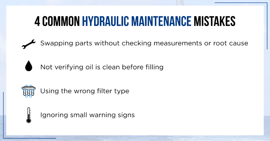
Common Mistakes to Avoid
- Replacing parts without confirming measurements. Swapping pumps or valves when issue was cleanliness, fluid degradation, or temperature problem wastes time and money.
- Ignoring new oil quality. Filling system with “new” oil that’s already contaminated undermines cleanliness goals.
- Using filters with only nominal ratings when absolute filters are needed to protect tight-tolerance components.
- Skipping small signs: odd temperature shifts, small noise changes, early flow or pressure drift. These signs often precede major failure.
Bringing It All Together: SIT’s Approach
At Supreme Integrated Technology, we believe in solving root causes, not symptoms. When a customer reports declining hydraulic performance, the troubleshooting process may follow a sequence such as:
- Collect system documentation and a current fluid sample.
- Measure temperature, pressure, and flow under operating conditions.
- Analyze fluid: viscosity, water content, cleanliness, and wear metals.
- Inspect filtration, coolers, and reservoirs for potential design issues.
- Test or observe valves, actuators, and pumps for internal leakage or worn components.
- Prioritize corrective actions: fluid replacement or regeneration, filter upgrades or offline polishing, component repairs, cooling enhancements, or improved reservoir practices.
This methodical process helps reduce downtime and restore system reliability to get you up and running.
Summary
When performance drops in a hydraulic system, it’s tempting to replace pumps or valves first. It’s important to note that many performance issues stem from fluid problems, contamination, overheating, or system-level issues like leaks and air entrainment. By documenting symptoms, analyzing fluid, setting ISO cleanliness targets, and systematically measuring pressure, flow, and temperature, you can better find the root cause. And once you’ve fixed it, adopting proactive maintenance, better filtration, and clean handling practices ensures the problem doesn’t repeat. That’s how SIT keeps systems running strong and engineers confident.
FAQs
1. How frequently should I run fluid analysis on my hydraulic system?
Depends on usage. For heavy-duty continuous operation, monthly or even bi-weekly; for moderate use, quarterly. Key is consistency so you can spot trends rather than one-off spikes.
2. What ISO cleanliness code should I aim for?
Pick the target based on most sensitive component. For large pumps and less critical valves, a code like ISO 19/17/14 may do. For tight tolerances, precision valves, or high-pressure systems, aim for something like 16/14/11 or better.
3. Can heat alone cause performance drops even if fluid and components look fine?
Yes. Elevated temperature lowers fluid viscosity, increases internal leakage, accelerates seal wear and oxidation. Heat can be root cause even if fluid looks and smells acceptable.
4. How do I detect internal leakage if nothing is visibly leaking?
Measure performance under load vs idle. If force or flow drops significantly under load, or actuator drift occurs, internal leakage is likely. Ultrasonic detection can find leak paths, and pressure drop tests across valves or pump can help locate problematic parts.
5. Is new hydraulic oil always clean enough to go into the system?
Rarely. Even new oil can carry contaminants from drums, bulk storage, or handling. Best practice: pre-filter new oil, clean filler caps, use dedicated hoses, and measure contamination before topping up or filling reservoirs.
Contact SIT for all your hydraulic-related needs.